
Wetenschap
Zelf-uitgezonden oppervlaktegolfingen in dynamische breuk van silicium eenkristal
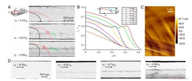
Dynamisch scheurfrontgedrag in steady-state (110) splitsing van de monokristallijne siliciummonsters onder pure buiging. (A) Morfologieën van het (110) splitsingsvlak (xy-vlak) van de as-sawn monsters bij verschillende steady-state scheurvoortplantingssnelheden versus de scheur plant zich voort langs de [110] richting (x-as). De Wallner-lijnen en scheurfronten worden benadrukt door de zwarte en rode rondingen, respectievelijk. De lokale knikken van het scheurfront worden gemarkeerd door de rode gestippelde cirkels en de oppervlaktegolfingen worden gemarkeerd door de groene lijnen. (B) Genormaliseerde lokale scheurfrontsnelheid vl/cR als functie van de genormaliseerde verticale positie y/h langs het scheurfront, voor zeven experimenten met verschillende vs. inzet illustreert de monsterdikte h en de hoek θ die de lokale normaalrichting van het scheurfront vertegenwoordigt (rode curve). (C) AFM-meting van de lokale voorste knikzone toont de opkomst van de oppervlaktegolfingen. (D) Morfologieën van het (110) splitsingsvlak van de oppervlaktegepolijste monsters bij verschillende vs. fractuuroppervlakmorfologieën vertonen het spiegelachtige kenmerk bij vs =0,59cR en de aanwezigheid van oppervlaktegolfvormingen bij vs =0,67cR (onder 0,45 ± 0,01 uur), 0,74cR (onder 0,51 ± 0,02 uur), en 0,80cR (minder dan 0,59 ± 0,02 uur). Krediet:PNAS, doi:https://doi.org/10.1073/pnas.1916805117
Wanneer een dynamische scheur zich voortplant door materiaalheterogeniteiten (materiaalverschillen), elastische golven worden uitgezonden om de scheur te verstoren en de morfologie van het breukoppervlak te veranderen. Wanneer een scheur zich voortplant langs preferentiële splitsingsvlakken van ruwheidsvrije (ruwheidsvrije) kristallijne materialen, onderzoekers verwachten een glad scheurfront en een spiegelachtig breukoppervlak. In een nieuw rapport dat nu is gepubliceerd op de Proceedings van de National Academy of Sciences ( PNAS ), Ming Wang en een onderzoeksteam in Mechanica aan het Franse Nationale Centrum voor Wetenschappelijk Onderzoek (CNRS) in Frankrijk, de Huazhong Universiteit voor Wetenschap en Technologie en het Hubei Key Laboratory in Wuhan, China, vertoonde karakteristieke scheurvoortplanting in een enkel kristallijn silicium zonder materiële oneffenheden (materiaalruwheid). Het scheurfront vertoonde een lokale knik tijdens scheurvoortplanting met hoge snelheid en genereerde periodieke breukvlakgolfvormingen of rimpelingen. Het fenomeen groeide van angstrom (Å) amplitude tot een paar honderd nanometer (nm) om zich met een lange levensduur bij een frequentieafhankelijke snelheid en met een schaalafhankelijke vorm voort te planten. De lokale frontoscillaties vertoonden het kenmerk van solitaire golven en Wang et al. noemde de niet-lineaire elastische golven "golfgolven".
In de materiaalkunde, scheurvoortplanting kan leiden tot catastrofaal materiaalfalen, en daarom, materiaalwetenschappers hebben de dynamische eigenschap decennialang intensief bestudeerd, maar de details blijven uitdagend. Volgens de lineaire elastische breukmechanica, een scheurpunt in een tweedimensionaal (2-D) medium kan worden beschreven als een energieput waarrond dissipatie optreedt voor energievoortplanting. In 3D-systemen wordt de lokale scheursnelheid bepaald door de lokale energiebalans om de hele vorm van het scheurfront te regelen. In het huidige werk, Wang et al. rapporteerde specifieke breukvlakgolfvormingen in de eenkristalsplitsing van silicium die opduiken in scheuren met hoge snelheid. Ze konden de morfologie niet verklaren met behulp van deflectiescenario's waarvan tot nu toe bekend was dat ze de splitsing van siliciumkristallen beschrijven. Het team stelde daarom voor dat zelf-emitterende golvingen (rimpelingen) sporen zijn van verschillende niet-lineaire elastische golven die bekend staan als golvingsgolven die uit de breukenergiefluctuatie kiemen met een kritische scheursnelheid. De golfgolven deelden ook specifieke eigenschappen met de scheurfrontgolven. Het team benadrukte in dit werk twee intrigerende kenmerken van golfgolven:inclusief niet-lineaire dispersie en deeltjesachtige interactiedynamica.
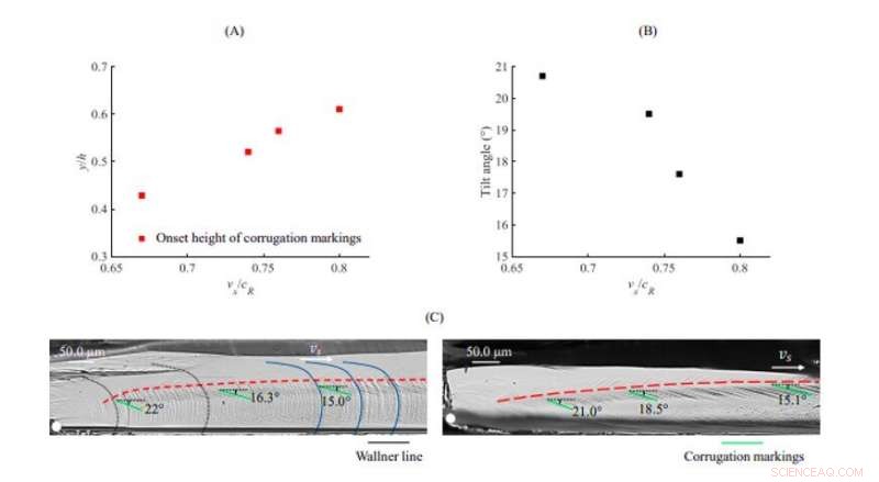
Afhankelijkheid van de oppervlaktegolfvorming van de scheursnelheid. (EEN), Genormaliseerde beginhoogte van de oppervlaktegolf als functie van vs. (B), Kantelhoek van de ribbels als functie van vs, gemeten vanaf Fig. S2. (C), Fractuuroppervlakmorfologieën bij het begin van de scheur voor het als-gezaagd (links) en oppervlak-gepolijst (rechts) monster met vs =0.8cR. De scheurinitiatievlek wordt weergegeven door het witte punt. De zwarte gestippelde curven vertegenwoordigen de variant Wallner-lijnen tijdens de scheurversnelling, terwijl de zwarte vaste curven de constante Wallner-lijnen vertegenwoordigen wanneer de scheur het stationaire regime bereikt. De variatie van de beginpositie en de hellingshoek van de golvingen worden gemarkeerd door de rode stippellijn en de groene lijn, respectievelijk. Krediet:PNAS, doi:https://doi.org/10.1073/pnas.1916805117
Breukexperimenten om de oppervlaktekenmerken te bestuderen
Wang et al. voerden de breukexperimenten uit op als gezaagde monokristallijne siliciumplaten onder zuivere buiging om de (110) splitsing te vormen. De bindingsspanning was normaal op het breukoppervlak om zich voort te planten onder een zuivere openingsmodus. Door de verschillende groottes van de zaadscheuren, de wetenschappers verkregen een breed scala van steady-state scheursnelheden, met een Rayleigh-golfsnelheid (scheursnelheid) gelijk aan 4, 460 m/s voor de (110) [110] richting van het kristal, om de scheurdynamiek te onderzoeken. De invariante vorm van de Wallner-lijnen, d.w.z. lijnen die het gevolg zijn van het zich voortplantende scheurfront en de afschuifgolven, onthulden de stationaire voortplanting van het hele scheurfront. In een scenario met lage snelheid, het lokale scheursnelheidsprofiel nam monotoon af van onder naar boven langs het scheurfront, terwijl in scenario's met hoge snelheid, de lokale knik vertaalde zich in een fluctuatie.
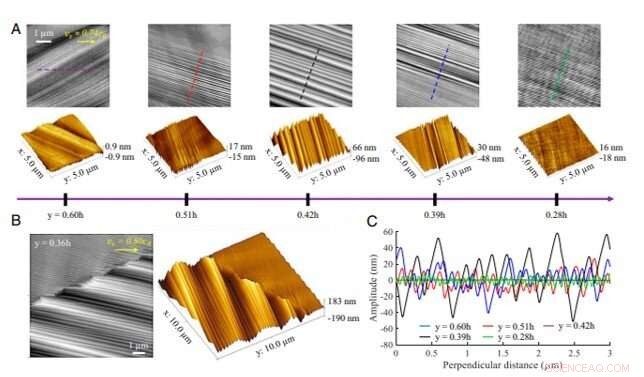
AFM-meting van de breukvlakgolvingen in de gepolijste monokristallijne siliciummonsters. (A) Topografieën van de oppervlaktegolven bij vs =0,74cR op verschillende hoogten. (B) Instorting van eerdere golvingen en opkomst van nieuwe bij hogesnelheidsscheurinstabiliteiten bij vfo =0,80cR. (C) Profielen van de oppervlaktegolven (langs de loodrechte richting van de golfrug) in verschillende levensfasen bij vs =0,74cR. De profielen zijn geëxtraheerd langs de stippellijnen gemarkeerd in A met de bijbehorende kleuren. Krediet:PNAS, doi:https://doi.org/10.1073/pnas.1916805117
Het team voerde een tweede reeks experimenten uit op aan het oppervlak gepolijste siliciummonsters, die de Wallner-lijnen uitsloot om de nauwkeurige morfologische kenmerken van de breukvlakgolvingen te bestuderen. Oppervlaktegolvingen op twee tegenover elkaar liggende breukvlakken hadden betrekking op een piek-tot-dal match, die Wang et al. onderscheiden van de lokale plasticiteit vóór de scheurtip gepresenteerd als een piek-tot-piek match, en analyseerde ze met behulp van atomic force microscopie (AFM) metingen. Gebaseerd op vijf typische topografieën, the research team observed the amplitude grow from an angstrom level to a maximum roughness of 100 nm. The team noted high-speed crack instability, which induced an abrupt crack path deviation to extend along the local front. The surface corrugations extended along various crystallographic directions depending on the crack speed and did not coincide with a specific crystal plane.
Different stages of crack propagation
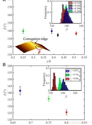
Distribution of angle β between corrugation planes. (A) Variations of β as a function of the normalized vertical position y/h at vs =0.74cR. The mean values of β and the standard deviations were determined from the histograms of β shown in Top Right Inset, which were computed from the profiles of the corrugations measured perpendicular to the corrugation ridge at different life stages presented in Fig. 2A. Schematic drawing of β is shown in Bottom Left Inset. (B) Dependency of β on vs. The mean values of β and the standard deviations were determined from the histograms of β shown in Inset, computed from the profiles of the corrugations measured perpendicular to the corrugation ridge in the zone where the corrugations extend with the maximum amplitude at different vs. Credit:PNAS, doi:https://doi.org/10.1073/pnas.1916805117
All surface corrugations exhibited a wave-like feature along the perpendicular direction, which Wang et al. measured to reveal geometrical characteristics of the corrugations. They dented the angle between the corrugation planes (denoted β) and observed its dependence on the crack speed. The surface corrugations extended along various crystallographic directions depending on the crack speed without coinciding with any specific crystallographic plane. The team revealed the long-lived propagation to be generated by highly localized out-of-plane agitations along the crack front.
The team further investigated the characteristics of the local crack front oscillations with periodic surface corrugations, where the orientation of the corrugations (denoted α) changed with the wavelength. The α also correlated with the width of the corrugations and with nucleation triggered by high speed crack instabilities. Wang et al. observed an increased wavelength and amplitude during the growth of the crack front oscillations, which subsequently decreased during decay of the oscillations. The team then highlighted particle-like interaction behavior of the local front oscillations. Bijvoorbeeld, when a fast-moving oscillation met a slow one, they showed particle-like collision and the fast-moving oscillation decayed and de-accelerated, while the slow oscillation grew and accelerated, meanwhile the linear correlation between the wavelength and amplitude retained.
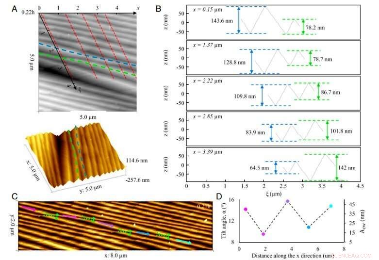
Collision behavior of crack front oscillations. (A) Topographies of the surface corrugations at vs =0.80cR. The ξ axis is the tangent direction of the crack front. Corrugation markings are generated by the collision of front oscillations, as highlighted by the blue and green dashed lines, respectievelijk. The corrugation markings exchange their orientation α after the collision. (B) Sequences of shape evolution of the front oscillations during the collision mentioned in A. The five sequences along the x direction are highlighted in A by the red dashed lines. At x =0.15 µm, different front oscillations propagate at vfo =0.965cR (blue) and vfo =0.935cR (green), respectievelijk, and then they exchange their speeds at x =3.39 µm. (C) Topographies of the surface corrugations at vs =0.74cR, y =0.21h incorporating successive collisions that result in successive phase shifts, as highlighted by the green dashed arrows. (D) Simultaneous variation of α and Afo of the corrugation marking generated by successive collisions of front oscillations, measured from the arrows with the corresponding colors in C. Credit:PNAS, doi:https://doi.org/10.1073/pnas.1916805117
Op deze manier, the collision events further revealed nonlinear characteristics of crack propagation, where particle-like interactions of the front oscillations were similar to solitary waves. During the collision, the two pulses exchanged their speeds and shapes for a resulting phase shift. In dit onderzoek, Wang et al. considered the front oscillations as nonlinear elastic waves and named them "corrugation waves" as they produced out-of-plane ripples (corrugations) on the fracture surface. The corrugation waves were continuously self-emitted from the moving front to propagate with the characteristics of solitary waves. The initial state of the corrugation waves depended on the source that created them. The nonlinear corrugation waves reported here differed from those described in previous through numerical modeling or experiments based on material asperities. Ming Wang and colleagues expect the results to provide additional insights on soliton-like crack front dynamics on the fracture surface of asperity-free (roughness-free) crystalline materials in materials science.
© 2020 Wetenschap X Netwerk
 Zonne-stoomgeneratoren kunnen van hout worden gemaakt, stof of sponzen
 Eigenschappen van het Bose Einstein-condensaat
 Wat zijn de verschillende soorten microscopie gebruikt in een microbiologisch laboratorium?
  Een nieuwe methode om zwavel in complexe moleculen te installeren
 Onderzoekers ontwikkelen 3D-printsubstraat met dynamische bindingen voor instelbare eigenschappen
 Gids uitgebracht ter ondersteuning van herstel na noodgevallen in Australië
 Wetenschapper test nieuwe technologie voor het verwijderen, voor altijd chemicaliën vernietigen
 Staat van het klimaat in de Drieklovenregio van de Yangtze-rivier in 2019
 Stof gezien dat uit Namibië de Atlantische Oceaan instroomt
 Nieuwe studie geeft antwoord op oude vragen over waarom tropische bossen zo ecologisch divers zijn
Hoofdlijnen
- Video van vier bobcats in een buitenwijk toont gezonde populatie
- Supermensen creëren door middel van genmanipulatie en meer
- Gebruik van microscopen in Science
- Hoe ribosomen het proteoom vormen
- De voor- en nadelen van klonen
- Waarom zou besnijdenis het risico van een man om AIDS op te lopen verminderen?
- Klonten als tijdelijke opslag
- Je lichaamscellen gebruiken en verzetten zich tegen kracht, en ze bewegen. Zijn mechanobiologie
- Welke effecten kunnen glycolyse remmen?
- Sproeidrogen om nieuwe materialen te produceren in industriële toepassingen
- Nieuw instrument om terrorisme te bestrijden
- Onderzoekers rapporteren nieuwe oxyfluorideverbinding voor fotokatalyse
- Operatie in een pil een mogelijke behandeling voor diabetes

- Kunstmest gemaakt van urine kan ruimtelandbouw mogelijk maken

 Hoe complexiteitswetenschap snel afwijkingen in klimaatrecords kan detecteren
 Kunnen zonnebatterijen worden opgeladen met gloeilamp?
  Wil je het snoer doorknippen en toch CNN krijgen?
 EU kondigt financiering aan voor Ariane 6 en andere ruimtetechnologie
 Horizontale afstand berekenen
 Gebruik van de oscilloscoop
  Lijst van vormen voor bladidentificatie
  17 doden door tropische storm in El Salvador en Guatemala
- Elektronica
- Biologie
- Zonsverduistering
- Wiskunde
- French | Italian | Spanish | Portuguese | Swedish | German | Dutch | Danish | Norway |

-
Wetenschap © https://nl.scienceaq.com

